I bought an Amiga 500 as my first computer in 1988. I later sold it and bought Amiga 2000, so this is not the same machine I used to own. Instead, I got this one from a friend in late 1990’s for free as it was broken. The problem was easy to fix – there were just some broken solder joints in the power supply after it had been dropped.
I’ve been upgrading this machine already, but need to redo some of the stuff, so here it is almost in the original shape. The only difference is that the Kickstart ROM is replaced from the original version 1.2 to version 1.3. There can be some compatibility issues in some games with 1.2, so as I had an extra 1.3 ROM available, I plugged it in.
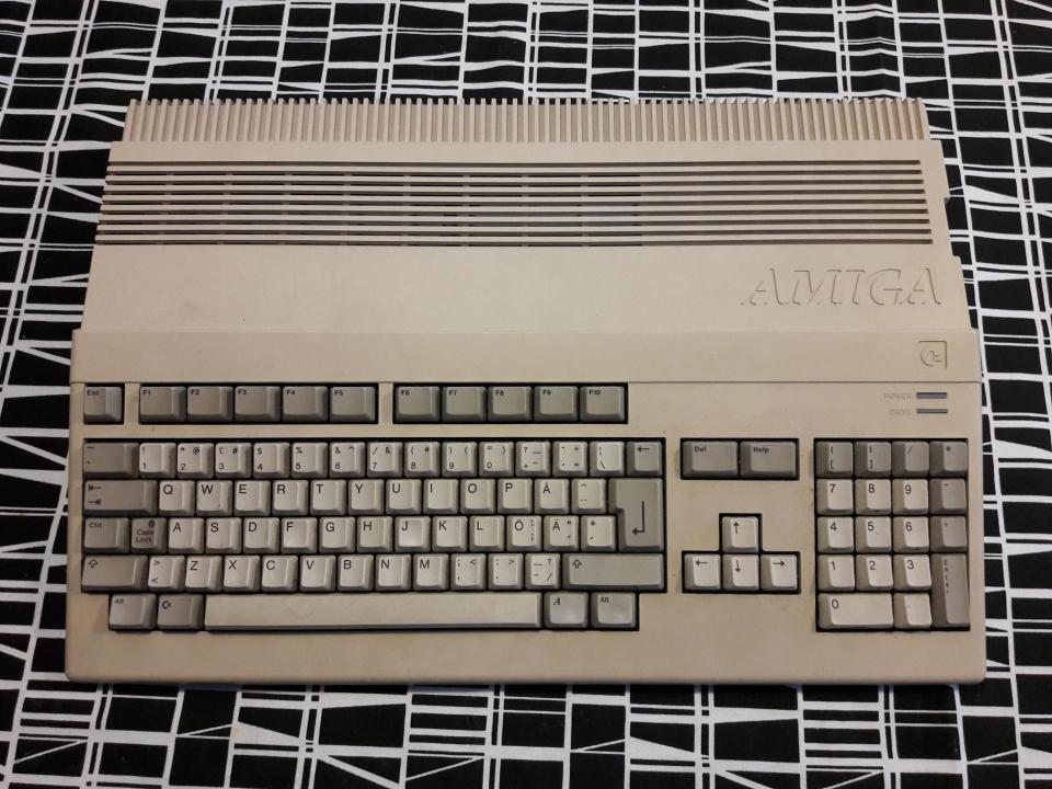
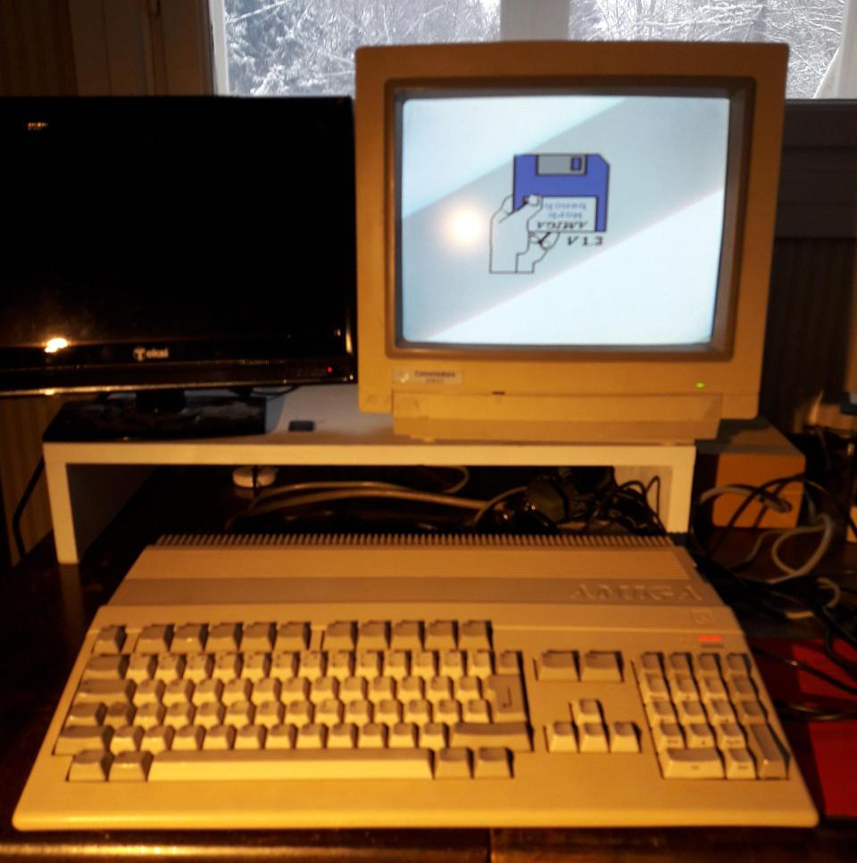
From the outside this looks like any Amiga 500. Keyboard layout is Finnish.
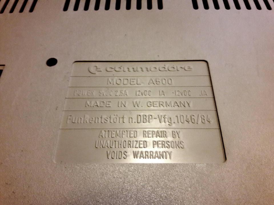
Note the “Made in West Germany”. We still had West and East Germany back then. Oops, I think I might have voided the warranty!
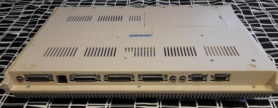
The back panel has typical D-sub connectors of the time, and some RCA connectors. The power connector is a strange rectangular DIN connector. Quite hard to find these days. Mouser has stocked these with numbers 161-0215 and 171-4405, manufacturer is Kobiconn. Power Dynamics has made these as well, but they are discontinued.
Also the monitor connector is hard to source, although it looks like pretty normal D-sub, it is a rare variant with 23 pins. I’ve had to sometimes use 25-pin D-sub and saw out parts of it to make a monitor cable.
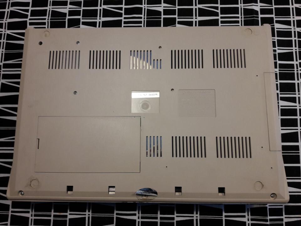
The cover can be opened by removing six phillips screws, three from the back edge and three from the front edge.
The computer is surprisingly big by todays standards. It has a full-size keyboard after all. There’s lots of empty room inside though, so they could have made it smaller. Maybe Commodore wanted to made it different from the Commodore 64 that was still being sold at the time.

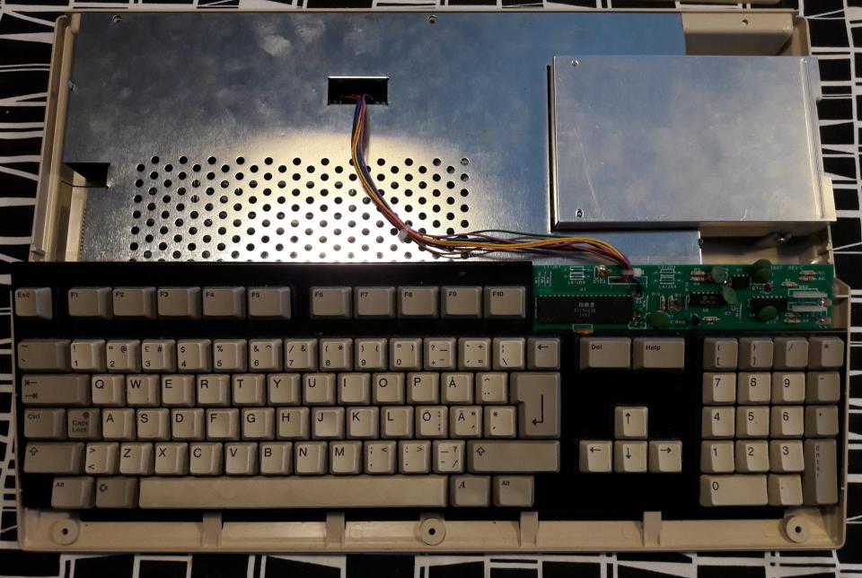
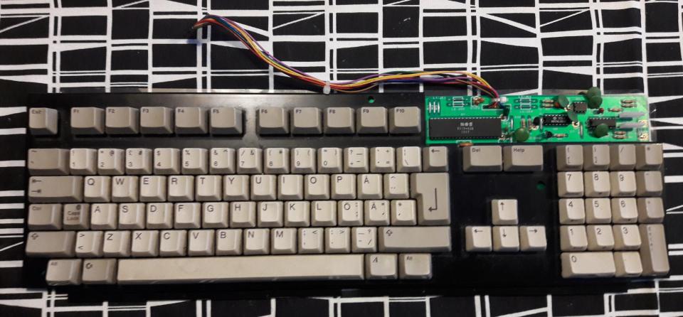
Below the cover is the keyboard. It can be unplugged from the header by simply pulling.
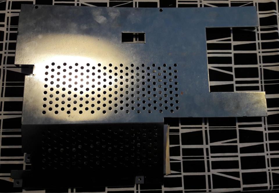
The metal cover under the keyboard is fastened with four phillips screws and some bent metal clips. The metal clips need to be straightened in order to remove the cover, I’ve left them in that position as otherwise they easily break off when bent and straightened repeatedly.
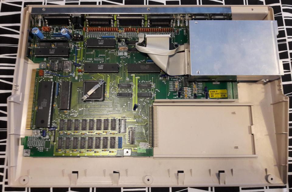
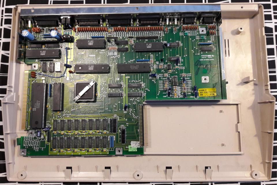
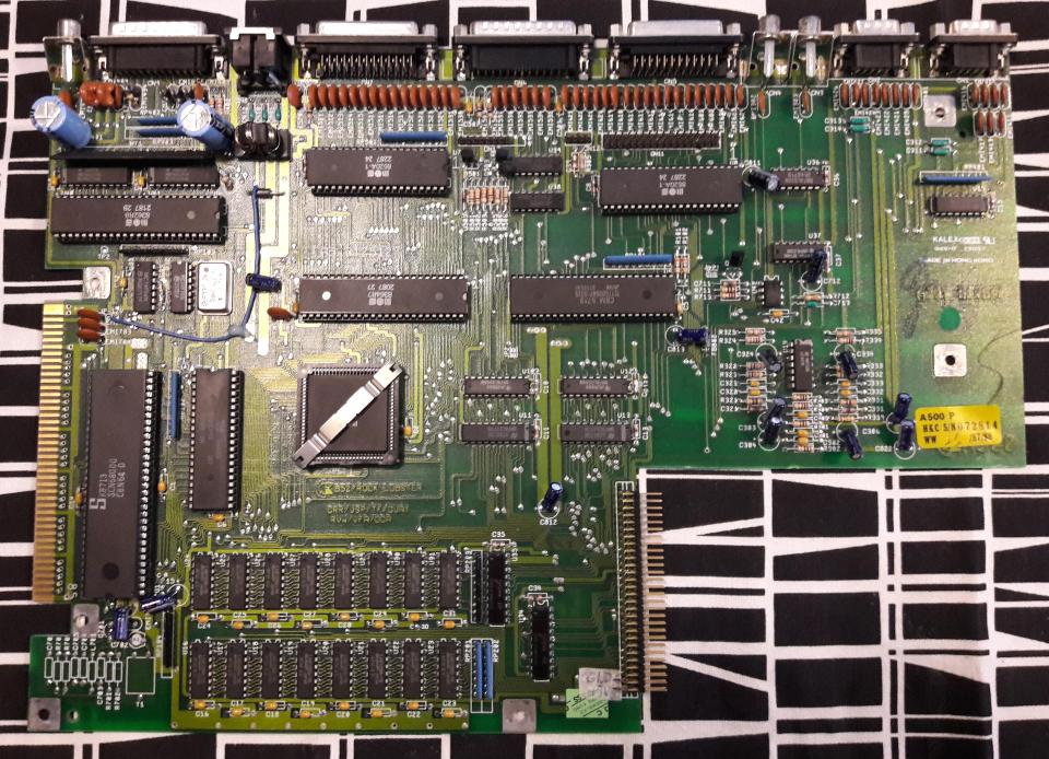
This gives access to the motherboard. As can be seen, this is an early revision 3 motherboard – see Amiga Hardware Database entry. Revision 3 means that some hardware modifications are a little bit more difficult to do than with newer motherboard revisions.
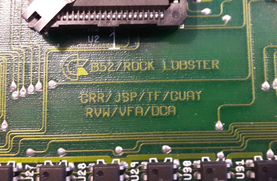
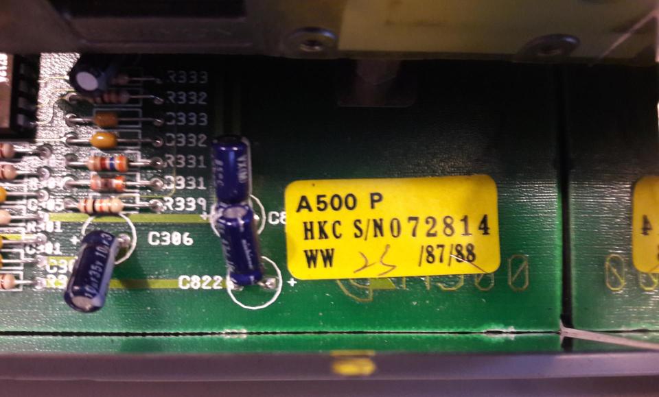
It seems that this was manufactured in 1987 or 1988. 1988 is either marked or crossed out, hard to tell. Probably 1988, so yay, it’s 30 years old this year!
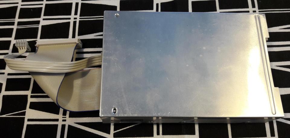
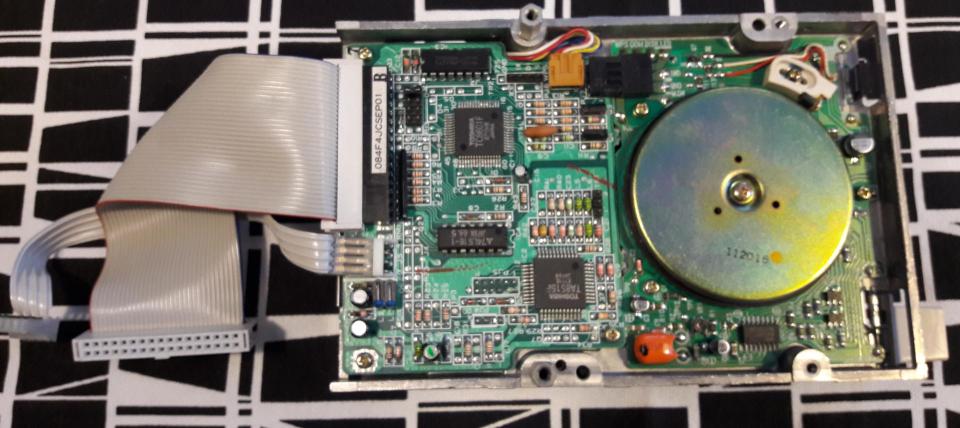
For complete removal of the motherboard, the disk drive has to come off first. It’s held by four screws, one from the side and three from the bottom. These are different from the other screws, so they shouldn’t be mixed. The connection cables on the motherboard can be just pulled off.
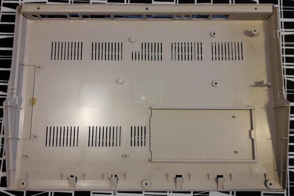
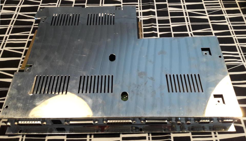
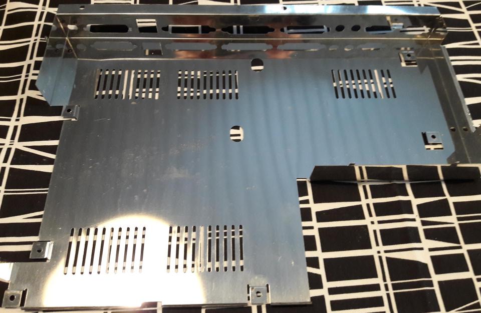
Now its’ possible to remove the lower part of the internal metal caging from the plastic cover.
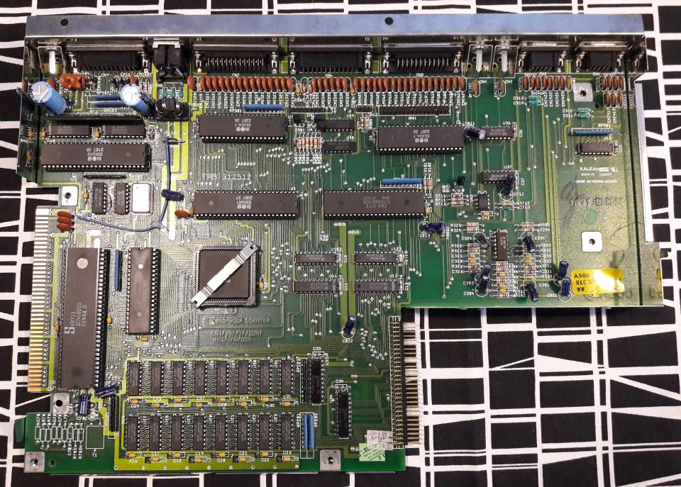
The motherboard is still attached to it by two screws at the edges of the monitor connector. When these are removed, it’s possible to pull the motherboard off from the metal caging.
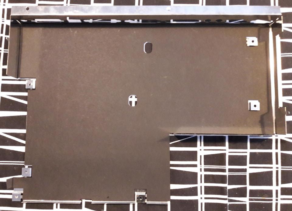
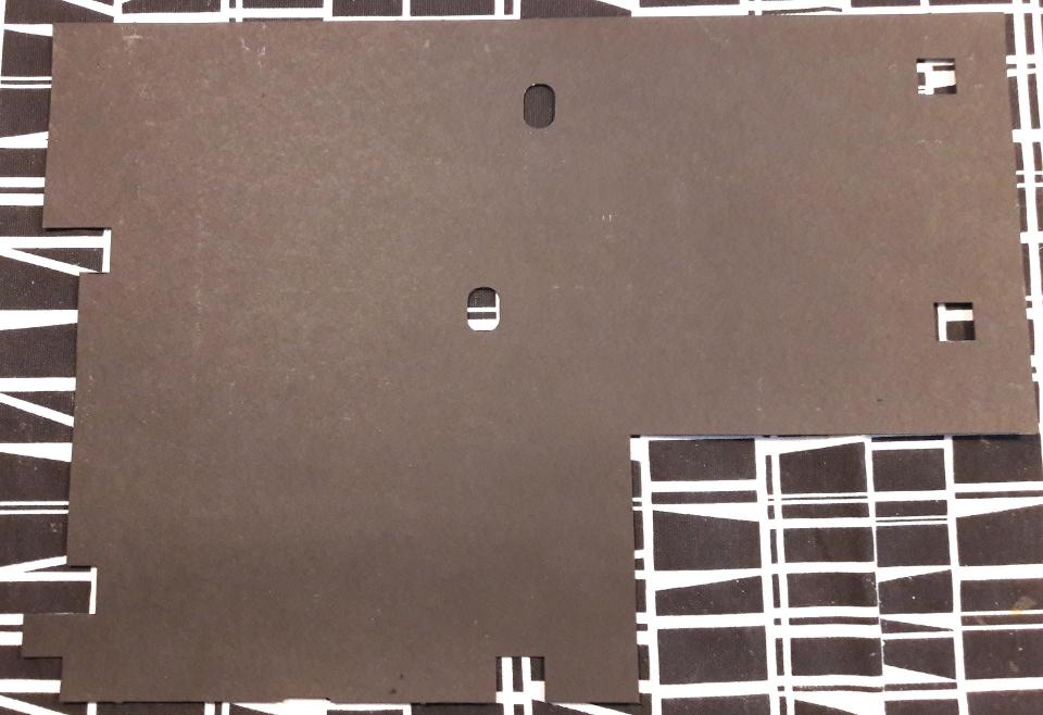
Between the metal and motherboard there’s an insulating sheet of some kind of cardboard. This prevents the metal from shorting the connections on the motherboard.
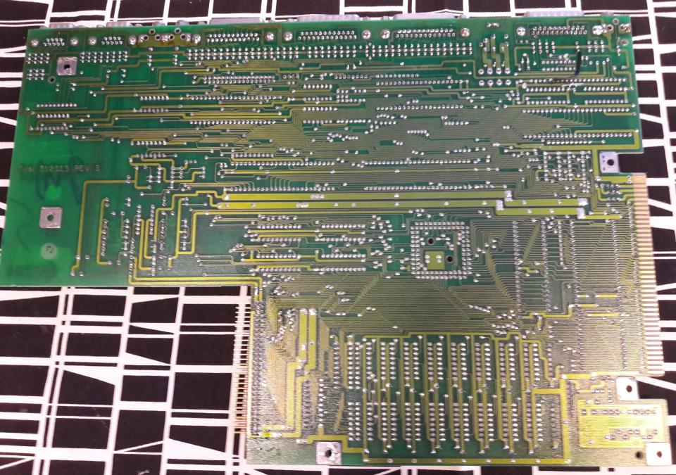
The other side of the motherboard reveals that this indeed is Revision 3 motherboard. Note also the fixes that are done to the board. These are from the factory, they had to correct the design manually after the boards were already manufactured.


Putting it back together basically is just the same process reversed. And then testing that it still works!

Hi there , hopefully i won´t disappoint you too much , but this is not a rev 3 Amiga 500 , although the board got this branding . It is a rev 5 type 1 Amiga 500 , got already the standalone oscillator instead off the discrete circuit .

Commodore started to produce this type of board obviously in ww 22/87 ( this one is ww 23/87 ) .
Fully Rev 3 A500s got a serial number below something around 40.000 , but this is really hard to say ,
cause unfortunately there are no sales numbers for every modell published
But this A500 got still this hard to find HiTec keyboard , the faulty TC Gary Chip and the transistor fix , so it is a very early rev 5 .
Made a pic of a rev 3 board long time ago , may have a look here :
Greetings
LikeLike
The board definitely is rev 3, rev 5 board has quite a different layout ( see https://amiga.resource.cx/photos/a500,3 vs https://amiga.resource.cx/photos/a500,1 ). This still has the same layout as earlier rev 3 boards, but the board is just populated differently. From the perspective of collecting value it may be significant difference how the board is populated, but from the modding perspective this is the rev 3 board that is most difficult to modify. For instance 1 MB chip RAM mod would be easier on rev 5 motherboard. On rev 3 motherboard it requires soldering a jumper wire directly to motherboard traces, on rev 5 there are solder pads for the mod (unless you take the route here: https://inkoovintagecomputing.wordpress.com/2018/02/15/amiga-500-chip-ram-expansion-with-no-motherboard-modifications/ ).
LikeLike